
Internal acoustics
The simplest measurement that indicates what a room "sounds like" is the reverberation time (RT). This shows how long it takes for a sound, such as a hand-clap, to die away. Rooms with a long RT sound "live", ones with a short RT sound "dead".
In concert halls for classical music, reverberation is known as "resonance" and the problem is often to get enough of it. But in most studios, too much reverberation is a nuisance, so special materials and structures are used to absorb sound to make it die away faster.
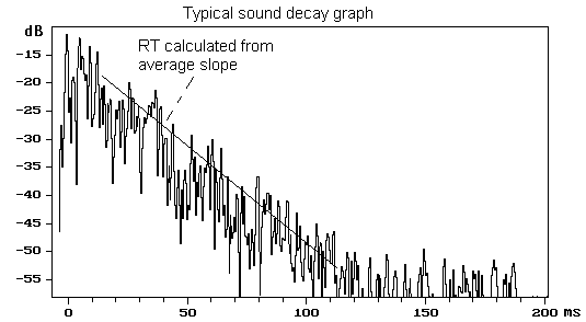
In theory the RT is measured by turning off a source of noise and measuring how long it takes for the sound to die away by 60dB. In practice, the die-away is measured over a smaller range, and the result worked out from the average slope of the decay graph. The result may be quoted as, for example, RT30 if a range of 30dB is used for the calculation. Don't try to correct an RT30 figure to a 60 dB die-away - this has been done already.
Whether a room sounds "live" or "dead" depends on the size of the room as well as on the RT. A small studio with an RT of 0.5 s will sound very live, but a large music studio with the same RT will sound dead.
The frequency response of the reverberation is important. A room that has a long die-away at low frequencies and a short die-away at high frequencies sounds "boomy". So RT is measured, not as a single figure, but either in octave bands or 1/3 octave bands. For a single-number measure, the average RT over a range of about 125 Hz to 2500 Hz can be used.
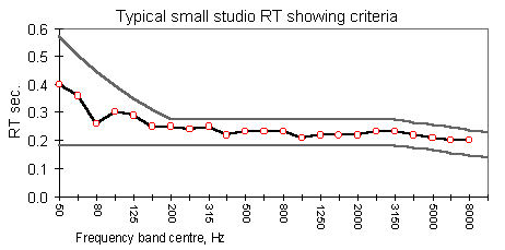
Absorbers for low frequency sound need to be deep, so they take up more space than those for high frequencies. Also soft materials such as carpets and fabrics, and most sorts of ceiling tiles, absorb mainly high frequencies. So in many practical room designs, there is a tendency for the RT to rise at low frequencies. This is acceptable up to a point, although rooms with little or no bass rise in RT usually sound more pleasant. (Apart from concert halls for classical music, for which many people think some bass rise of RT is a good thing.)
There is also a natural tendency for RT to fall at high frequencies. This is also acceptable and may even be a good thing. (In very large rooms, RT will inevitably droop at high frequencies due to absorption by the air.) Specifications for RT usually allow for a low frequency rise, and sometimes for a high frequency droop.
A typical specification would state an average value of RT with a tolerance of, say, plus or minus 10%. It might also contain a graph showing allowable deviations at high and low frequencies, similar to the grey lines in the graph above.
When comparing RT graphs, check the scale of the time axis. This is often linear, but some practitioners (including myself!) prefer a logarithmic scale that is thought to give a better indication of the subjective impression. This can make the same result can look very different!
For speech studios, average values of RT are usually specified between about 0.2 and 0.3 seconds. Smaller studios always have the lower values, but larger studios are more variable. Some users prefer even relatively large studios to be very dead, as it makes microphone placement less critical. (Large TV studios are usually as dead as possible, given their hard floors and space taken by equipment that's not available for aborbers.) Others prefer a more live sound that makes a room more comfortable to speak in. Very small rooms such as voice booths may have RT well below 0.2 seconds, and in practice such a low RT can be very difficult to measure.
RT is not the whole story
RT is far from telling you all there is to know about the internal acoustics. It's a general statistical measure, usually averaged over the whole room, so it can't say anything about local reflections or local resonances. There's no agreed way to measure such things that relates to what they sound like, so you can't put them in the spec - you have to rely on the designer's experience to avoid problems.
However it is possible to specify one fault that must be avoided - flutter echo. This happens when sound bounces backwards and forwards between a series of hard surfaces, repeatedly following the same path. Usually the problem is caused by just two hard surfaces, opposite and parallel to each other, although other arrangements can cause this problem:
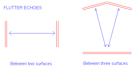
A flutter echo can be diagnosed with a sharp hand-clap, when the repeating reflections form a fluttering noise that give the problem its name. It is a problem only in rooms that are quite dead. In live rooms the gaps between the repeating series of reflections are filled by other reflections, so the effect cannot be heard.
Typical sources of flutter echoes are large windows parallel and opposite to each other. The cure in this case is to angle one or both of the windows by enough to prevent the flutter. Ten degrees angle between the two surfaces is adequate.
Your consultant will usually arrange acoustic treatment so that in the main part of the room, hard surfaces are placed oppposite to soft ones. Minor changes to room layouts are sometimes (always?) made at a late stage in the project, so it's important that this aspect of the acoustic treatment is maintained.
Another fault that a specification might outlaw is mechanical resonance. This occurs when such items as light fittings "ring" in response to a sound. Again, a hand-clap is a good tool for diagnosing such problems.
Control rooms
Control rooms have some special requirements that makes them different from studios.
For two-channel stereo, there is a requirement for good "phantom" images, from positions between the speakers. As the loudspeakers and listening positions are fixed, the acoustics can be optimised to ensure that his happens.
Generally, in rooms, people can tell quite well the direction from which a sound is coming. The ear-brain combination picks out the direction from the first sound that arrives at the ear, despite the large number of later reflections from walls and other surfaces. (The sound directly from the source is always first to arrive.) But in stereo the "sources" between the speakers are not real but "phantom" images. A combination of the direct sounds from the two speakers creates the illusion, but certain reflections from room surfaces can seriously upset it.
The reflected sounds that cause problems for stereo listening are those that arrive very closely after the direct sound, known as "early" reflections. In a normal rectangular room, early reflections that degrade the stereo image are likely to come from the ceiling, side walls and back walls. These early reflections can be reduced by putting sound absorbent material on the relevant parts of walls and other surfaces. However this may make the room too dead for comfort, and it may not reduce the level of reflections enough. For the most critical listening, it may be necessary to angle the surfaces to direct the early reflections away from the main listening position. This can lead to room designs looking, in plan, something like the following:
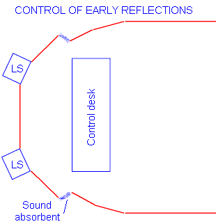
A prime cause of poor stereo is reflections from the surface of the control desk. This is not really the fault of the room, but it is a good idea to get the acoustic consultant to check the layout and make sure that such reflections are not a problem. For critical stereo listening, it is necessary to specify the level of these early reflections.
The reverberation time of a fairly large control room is often a little longer than would be suitable for a studio of the same size - say 0.3 s. This makes the room more comfortable to work in.
I hope this brief outline of studio acoustics is useful for professionals who have to deal with acoustic consultants, and try to make sense of their specifications and the results of acoustic tests. Feedback will be very welcome.
Tony Woolf
Phone or email for a free initial discussion about your project.
Phone 020 7624 2512 or click to contact us.
Text charts and images copyright Tony Woolf 2000 & 2007 unless otherwise stated.


